Definition: The upper run of cable chain operates without touching the lower run over the entire travel.The unsupported application is the most common for short travels within 10m.

LONGO cable chains are highly suitable for applications with long unsupported lengths, high speed and acceleration, and a long service life.

We recommend installing the fixed end of the drag chain at the midpoint of the stroke. In this case, the required lengths of the drag chain, cables, and hoses are the shortest, resulting in the lowest cost.

LK = S/2 + K

LK = S/2 + K + ΔM

All LONGO standard cable chains are manufactured with pre-camber (arch). This pre-camber enables longer unsupported lengths, increases the service life, and results in an actual installation height (Hz) that is greater than the nominal clearance height (H) when installed.

The specific Hz value for each cable chain can be found in its respective product description.

For applications with restricted space, we also offer cable chains without pre-camber — the NC cable chains.

We recommend pivoting mounting brackets as standard for unsupported applications.

Pivoting mounting brackets can compensate for the camber, decrease the load on the first chain link in operation and be installed more easily.

Exception: If the speeds exceed 10 m/s, accelerations exceed 20 m/s², or the clearance height is limited. In such cases, locking mounting brackets are recommended to keep the cable chains under the Hz measurement and avoid taking the cable chains off.

Definition: The unsupported distance between the moving end and the start of the radius arc of the cable chain.The maximum unsupported length depends on the chain series and the fill weight. The product page of each chain series provides a “Load Diagram” for reference.

Straight Unsupported Run FLG

FLG:The cable chain is either pre‑campered, completely straight, or exhibits a maximum sag (Ymax) ≤ 1/2ha of the chain’s outer height (ha).

We recommend linear overhead installation as your standard configuration. In this case, the drag chain will experience the least wear and vibration, generate the lowest noise, and be able to achieve the maximum speed, acceleration, and service life during operation.

Unsupported with permitted sag FLB

FLB:The sag is less than the minimum bending radius of the selected chain series.1/2 ha < Ymax ≤ Rmin.

Safety sagging is also permitted in many cases. When the drag chain operates under such circumstances, wear, vibration, and noise will increase, and the maximum allowable speed, acceleration, and service life will decrease accordingly.

Critical sag

The sag is more than the minimum bending radius of the selected chain series, Ymax > FLB

Dangerous sagging will greatly affect the service life of the cable chains and the safety of the equipment, which should be avoided during the design process. If dangerous sagging occurs after the cable chains has been used for a long time, it needs to be replaced.

Unsupported with overhang FLU

The sagging length of the cable chains when there is no support at the bottom

The overhead sagging length depends on the type of drag chain and the internal load. We recommend the maximum sagging length FLUmax ≤ 1/4 FLG.

When the unsupported length is insuficient, suppot may be a good solution. But speed and acceleration are limited, and noise and vilbration may arise.

A stronger cable chain is always the first choice if conditions are permitted. Three fundamental supports examples are detailed below. The supports can be made of rollers or trays.

1.One support
The unsupported travel can be increased by a maximum of 50% :
Smax = 3·FLG

2.Two supports
The unsupported travel can be increased by a maximum of 100%:
Smax = 4 FLG

3.Full supports
The unsupported travel can be increased by a maximum of 100%:
Smax = 4 FLG

Opposed
Opposed or nested is designed if the installation height and width are limited and the filed space needs to be increased. They are also good solutions for insufficient unsupported length.

Nested
A certain gap between the nested cable chains is needed for smooth running. The difference in bending radius of the adjacent cable chains is recommended: R1 - R2 > 3/2 ha

The operating noise of the cable chains depends on the following factors:

1. The ratio of bending radius to pitch R/P

The larger the R/P value, the closer the bending radius of the cable chain is to an arc, and the more smoothly it runs, with lower noise and vibration. The R/P value is very important for some applications required high accuracy. LONGO cable chains had optimised the ratio of inner height to pitch. We can also customize special specifications for your special applications

2.Installation conditions

The noise level is lowest when the cable chain is unsupported with straight and increases if sagging occurs or supports are added. The supporting surfaces should be flat and avoid interference during operation. Laying elastic elements such as PU padunder the cable chain can reduce the overall noise of the equipment.

3. The structure of cable chains

We are innovating the cable chains continuously to find more effective, simple and economical noise-optimised solutions. LONGO cable chains are designed with noise-optimized structures, which can significantly reduce operating noise.

4. Speed and acceleration

The higher the speed and the acceleration, the louder the noise. LONGO cable chains that have been tested reach a low decibel level even at high speed and acceleration.

Definition: The upper run of cable chain glides on the lower run or the supporting surface such as glide bars

When the stroke exceeds the designed range of the overhead cable chains, a sliding scheme can be adopted to achieve long-distance mobile power supply. The stroke can range from tens of meters to several hundred meters.

LONGO stroke sliding has been widely applied and proven to be an effective, safe and reliable application method.

We recommend installing the fixed end of the drag chain at the midpoint of the stroke. In this case, the required lengths of the drag chain, cables, and hoses are the shortest, resulting in the lowest cost.

LK = S/2 + K1

Gliding with one cable chain:Offset the centre of the travel △C

Gliding with two opposed cable chains :Restricted space, high load or two independent devices

We recommend pivoting mounting brackets as standard for gliding applications.

Pivoting mounting brackets can well adapt to the rotation of these chain links, decrease the load on the moving end links and avoid stress concentration.

If the moving end is not lowered:H=2R

Long unsupported length, critical sag and high internal stress of cable chain

Big mounting angle, easy to break when cable chain returning

If the moving end is lowered:H=3ha

Greatly reduce the unsupported length and relieve the internal stress of cable chain

The mounting angle is about 5, reducing the risk of breaking when cable chain returning

Reduce wear and vibration, Achieve long service life

The first chain links must be rotated if the moving end lowered.

Save installation space (smaller D1)

Reduce internal stress due to"S" shape of moving end

Avoid the cable chain rising up during operation.

The number of reverse-installed chain links nR depends on the type of drag chain and the bending radius R, and can be queried in the installation dimensions of each series.

Supporting the first chain links of moving end is usually necessary. The support plate can protect the moving end links against over-stressing and avoiding accidental break. The slope of the support plate is recommended to be 10°~15°, and it can support at least 3 moving end links or all rotated chain links.

Guide trough systems are necessary for the cable chain systems running stably in sliding applications. Various guide trough systems are available: modular, economical and easy to assemble. We recommend GuidEasy guide trough systems as standard for general guiding applications.

Galvanized steel - used in general applications, cost - effective

Stainless steel - used in outdoor applications and scenarios requiring corrosion resistance

1. CTR Deviation Compensation Device

When the equipment is operating over a long stroke, if the left-right offset perpendicular to the direction of the cable chains movement exceeds the allowable offset of the cable chains, a deviation compensation device (CTR) needs to be installed between the equipment and the moving end connector of the cable chains. The CTR can compensate for the excessive offset, preventing the cable chains from being laterally stressed, which could lead to increased wear, and even the risks of derailment and overturning.

3. Guide trough

The Guide trough must be installed on a horizontal base.

The internal height HGi of the Guide trough should be at least twice the external height of the cable chains’ link: HGi ≥ 2 ha.

The clearance between the inner side of the Guide trough and the cable chains is 5mm: BGi = Ba + 5

3. Glide bar

Slide strips should be installed when the cable chains has no self-support during long stroke operation. Slide strips can provide continuous support to the cable chains, ensuring smooth operation and reducing noise. We recommend using LONGO's engineering plastic slide strips. With a relatively low coefficient of friction (the coefficient of sliding friction for LONGO cable chains is approximately μ ≈ 0.2), they can reduce the driving force and wear of the cable chains, thus extending its service life.

Vertical hanging:

Definition: The cable chain operates in the vertical direction and the arc bending downwards.

With LONGO cable chain systems, travels of over 100m are possible in vertical hanging applications. The cable chains fulfils the function of orderly conduit bundling only and should not absorb any further tensile forces. All cables and hoses must be secured carefully to both ends of the cable chains with strain relief so that they bear their own weight.

A standard LONGO cable chain with camber is suitable for vertical hanging applications if enough space is available. lf space is restricted a cable chain without camber can be used - NC chain.

Required space for standard chain:Hz = 2 R + ha + z
Required space for NC chain:Hz = 2 R + ha
z = 20 ~ 100 mm(is depended on chain series)

We recommend locking mounting brackets as standard for vertical standing applications.
The cable chains can not sway with locking mounting brackets during the movement.

Without lateral acceleration

If the application has a purely vertical movement without lateral acceleration, a lateral support is not necessary.

With lateral acceleration

If the application has lateral acceleration, a lateral support is required. Lateral supports can be partially installed, but supports should be installed at least at the positions where the drag chain may swing. Option C in the diagram is preferred.

A: Without support: For applications without lateral acceleration

B: Planar support: For applications with lateral accelerationas illustrated

C: U-shaped support: For applications with lateral accelerationas illustrated

Definition: The cable chain operates in the vertical direction and the arc bending upwards.

The cable chain must bear its own weight and the weight of the cables and hoses in vertical hanging applications, therefore the pemmitted travel is much shorter. The cable chain is far less stressed and more stable in a hanging application, so vertical hanging would be a better choice if the space is allowed. All cables and hoses must be secured carefully to both ends of the chains with strain relief.

A standard LONGO cable chain with camber is suitable for vertical standing applications if enough space is available. lf space is restricted a cable chain without camber can be used - NC chain.

Required space for standard chain : Hz = 2 R + ha + z
Required space for NC chain : Hz = 2 R + ha
z = 20 ~ 100 mm (is depended on chain series)

We recommend locking mounting brackets as standard for vertical standing applications.

The cable chains can not sway with locking mounting brackets during the movement.

Without lateral acceleration

If the application has a purely vertical movement without lateral acceleration, a lateral support is not necessary.

With lateral acceleration

If the application has lateral acceleration, a lateral support is required. Lateral supports can be partially installed, but supports should be installed at least at the positions where the drag chain may swing. Option C in the diagram is preferred.

A: Without support: For applications without lateral acceleration

B: Planar support: For applications with lateral accelerationas illustrated

C: U-shaped support: For applications with lateral accelerationas illustrated

Definition: The cable chain is side-mounted and travels linearly in the horizontal direction.

Side-mounted is used for applications with restricted installation height instead of unsupported.

In lateral applications, using LONGO cable chain offers the following advantages:

1.Integrated lateral wear-resistant surfaces enable a long service life without the need for additional devices.

2.The chain side plates with mortise-tenon structures and the crossbars with wings significantly enhance the lateral stability of the cable chain (GeMotion series).

We recommend locking mounting brackets as standard for side-mounted straight applications.

The cable chains can not sway with locking mounting brackets during the movement.

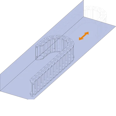
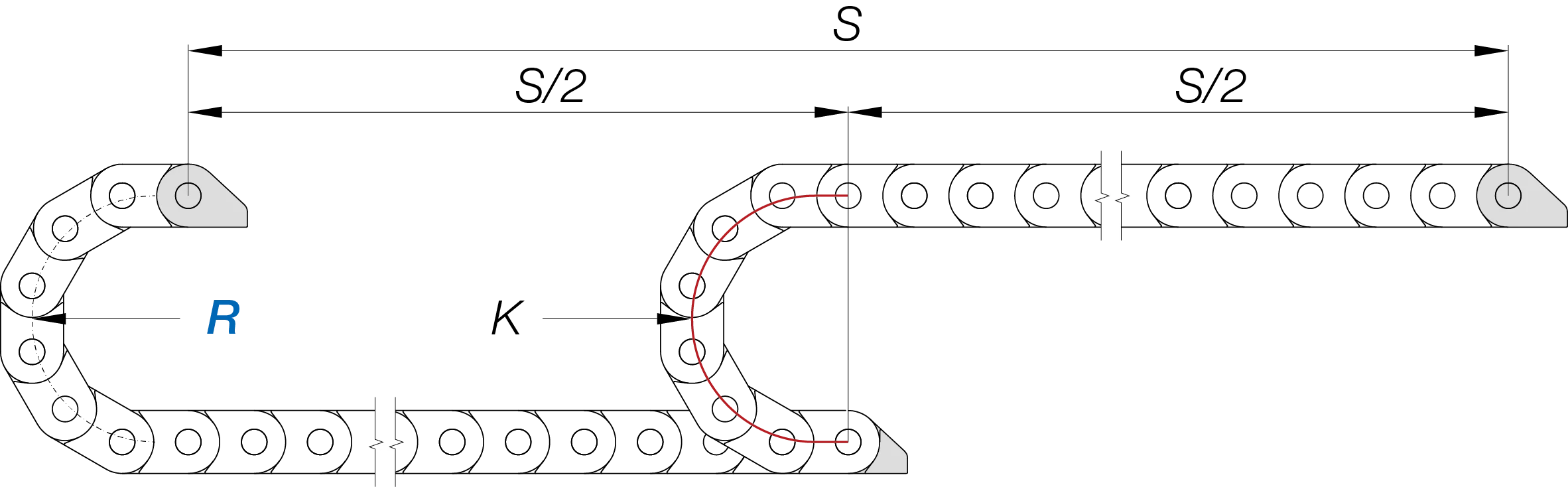
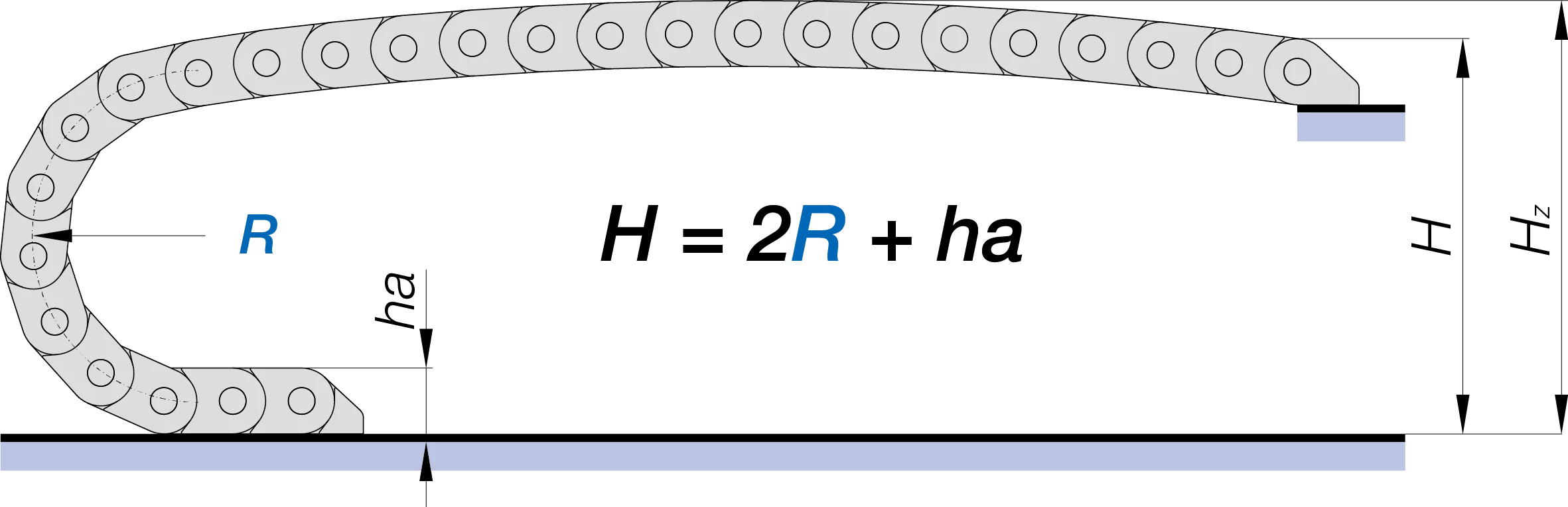
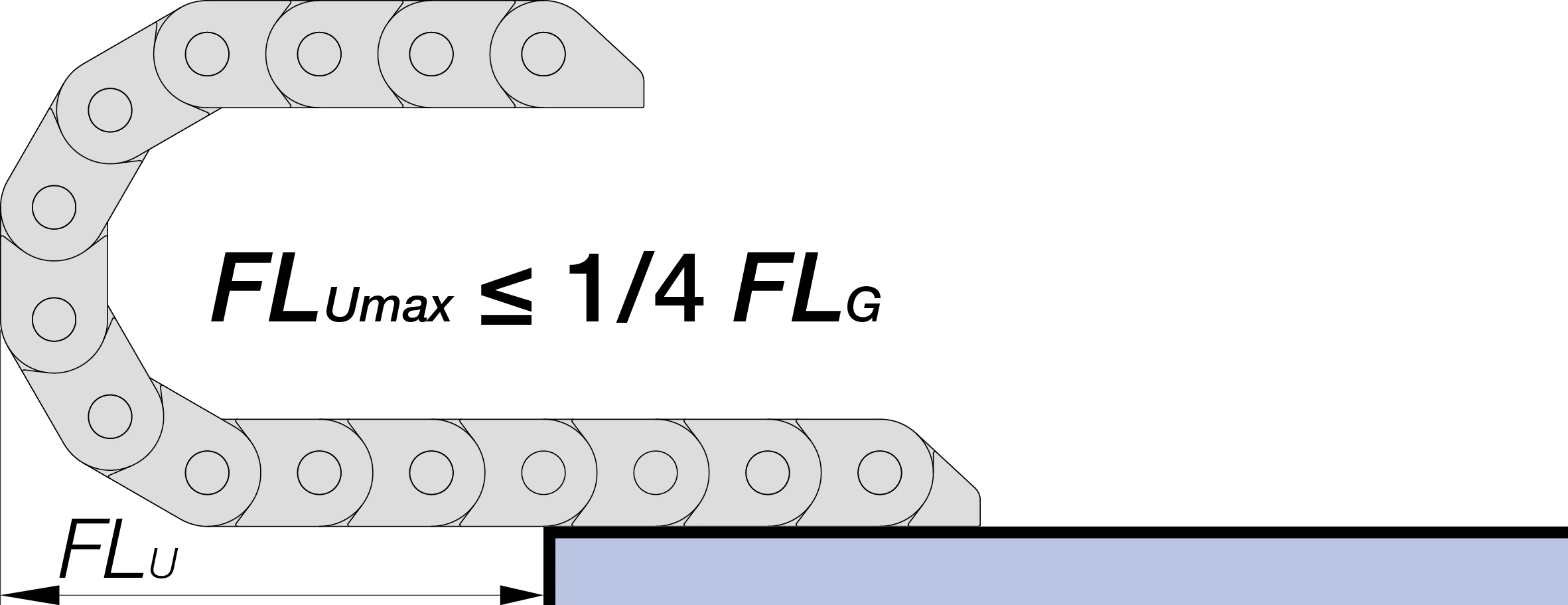
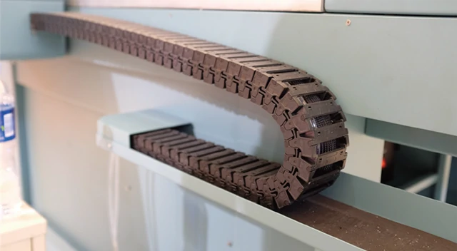
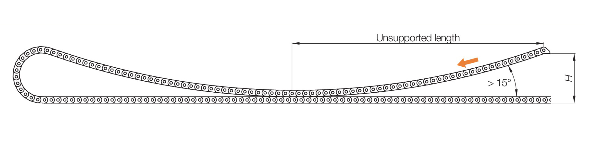
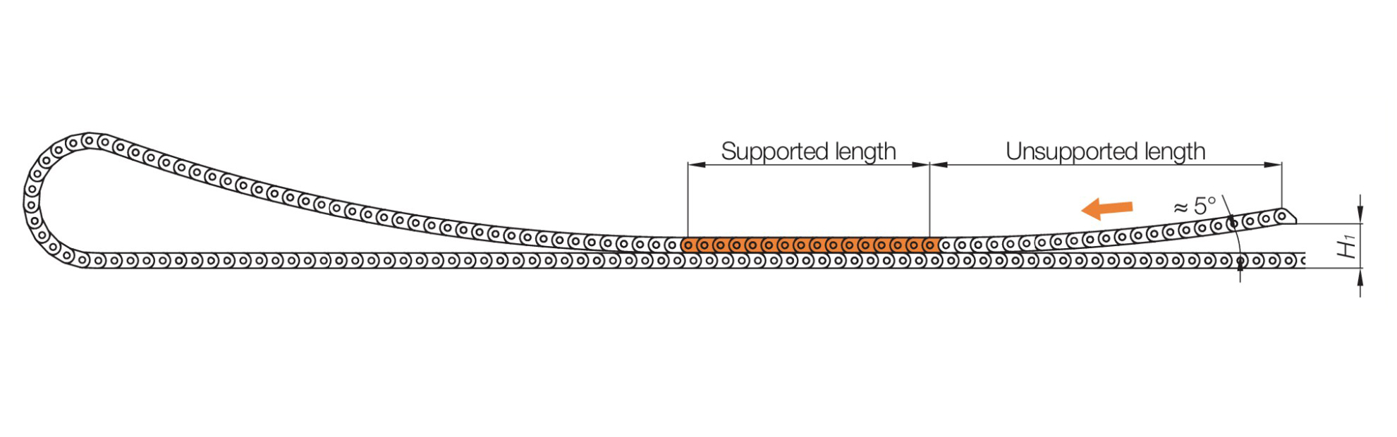
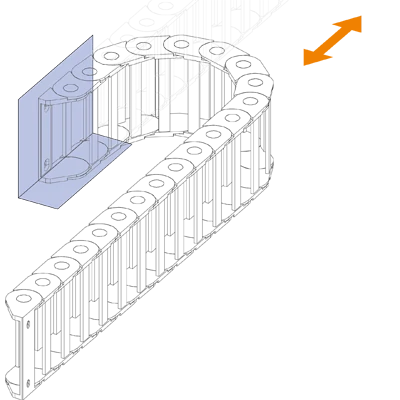
Side-mounted chains can be used unsupported to a limited extent. The unsupported length is dependent on the following factors:

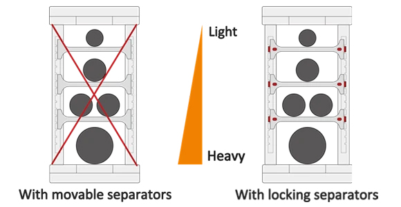
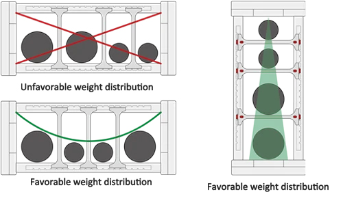
1. Fill weight: The greater the fill weight of the chains, the shorter the available unsupported length

2. Width of the chains: The wider the width of the chains, the longer the available unsupported length

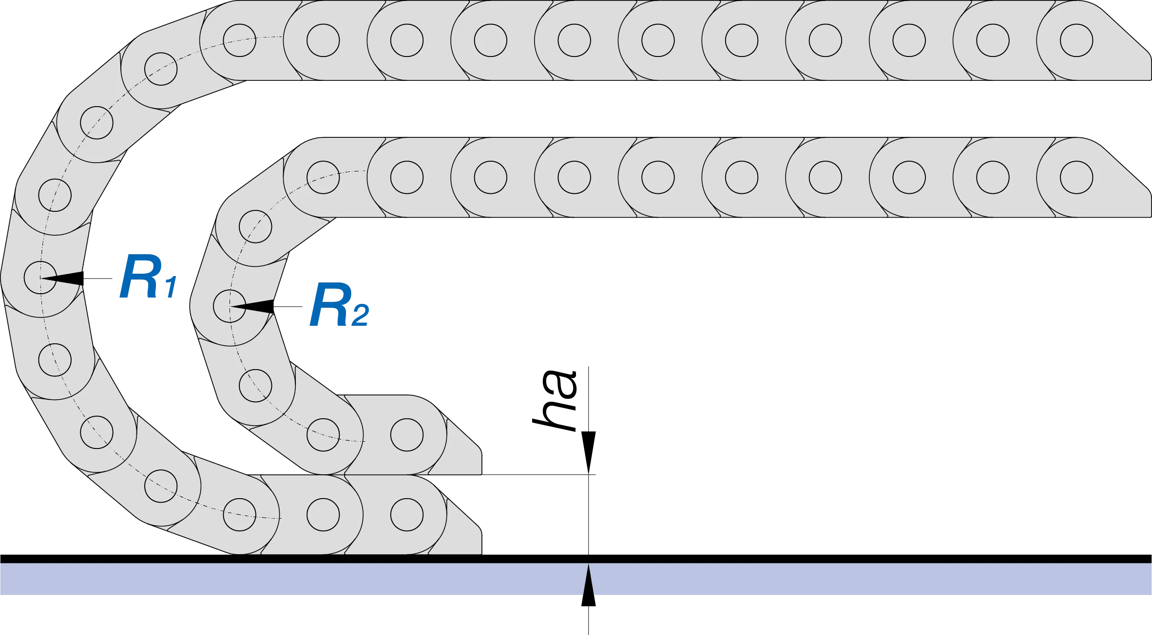
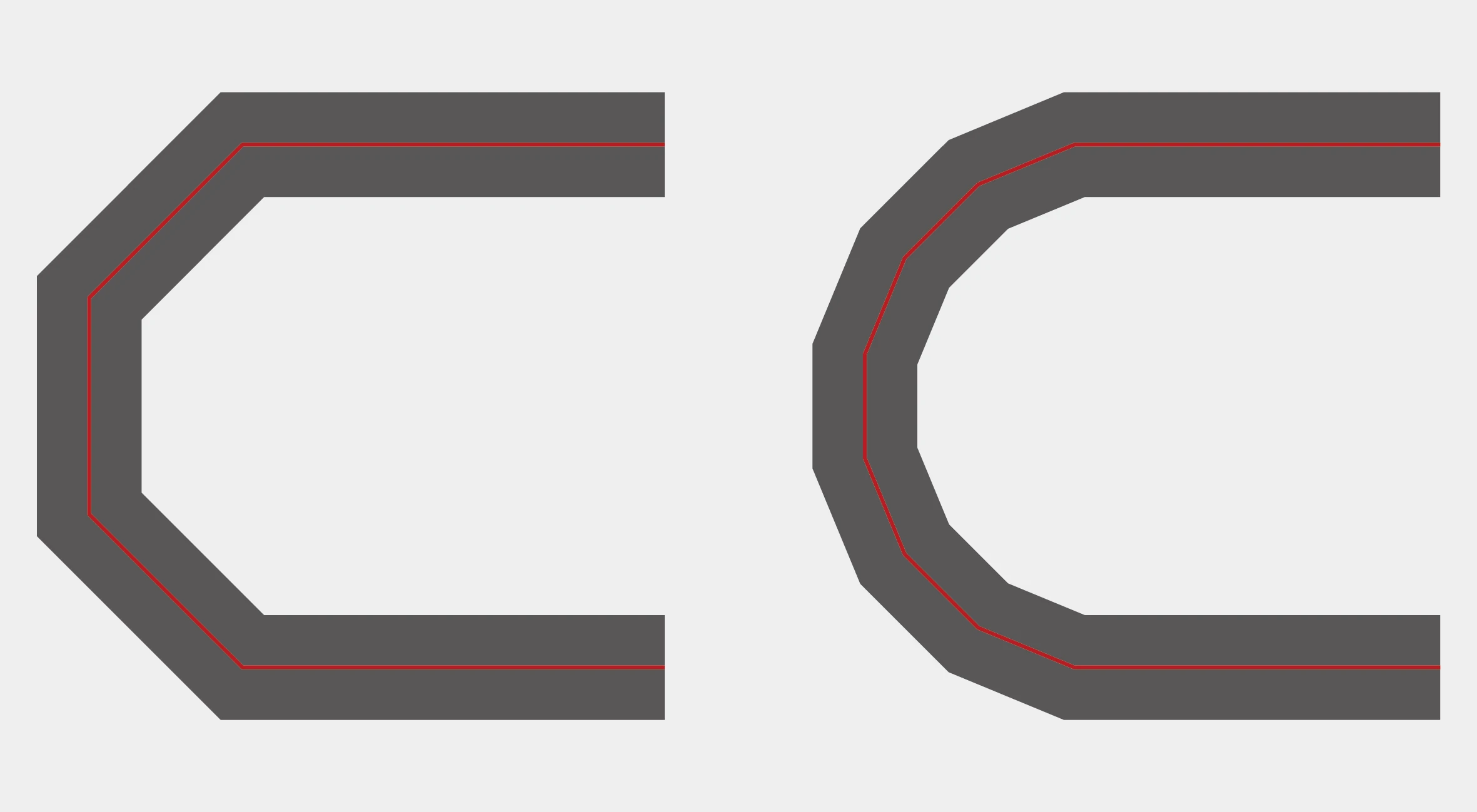
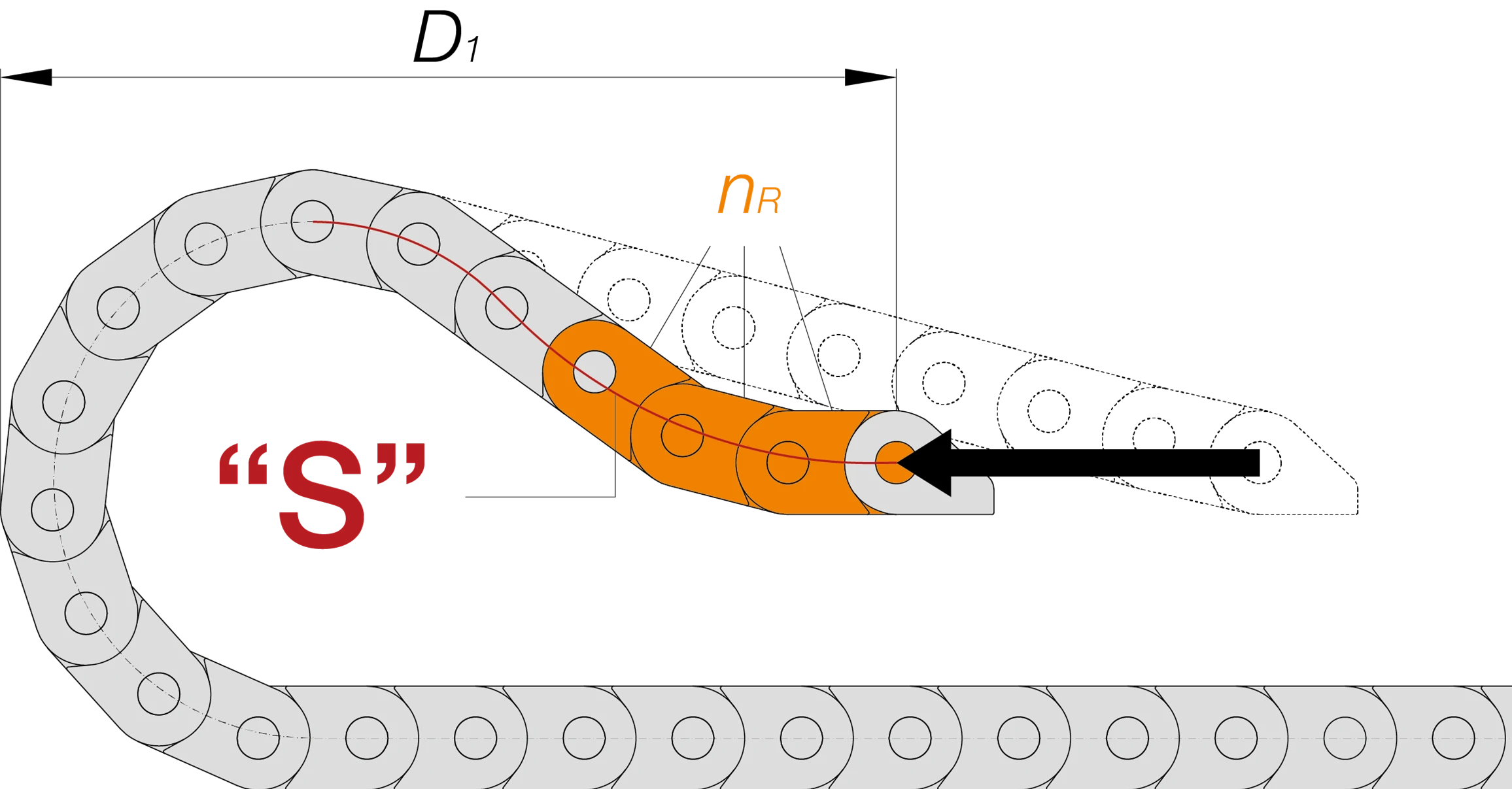
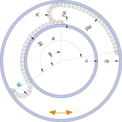
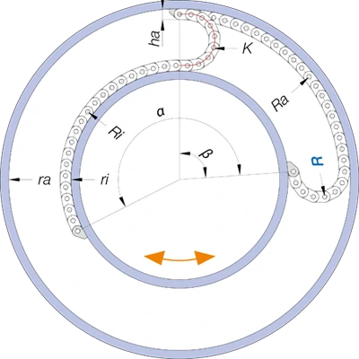
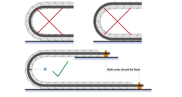
3. Bending radius: The smaller the bending radius of the chains, the longer the available unsupported length

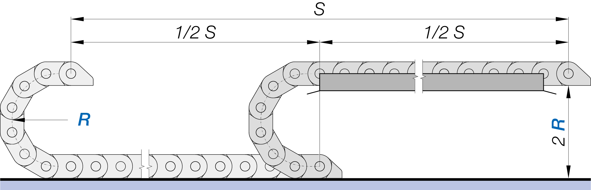
For applications with short travels and low fil weight, support is not necessary. If, however, the travels are long and the fill weight is high, the chains must then be supported either in whole or in part.
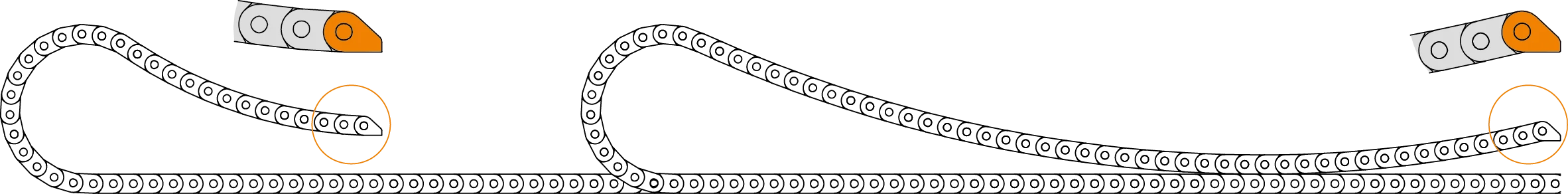
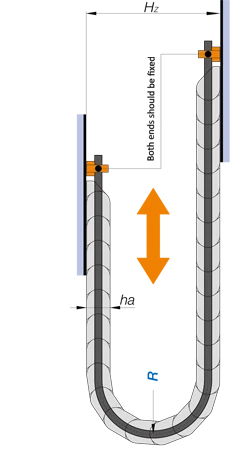
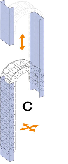
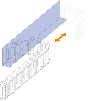
A. Without support

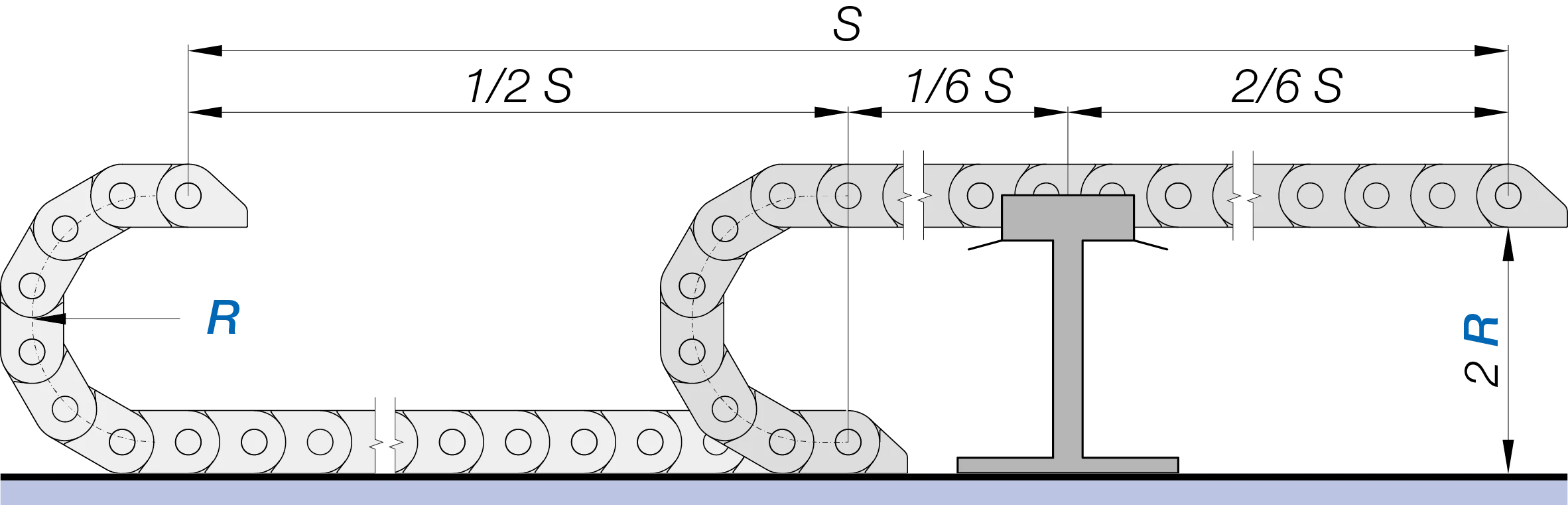
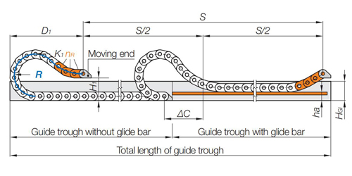
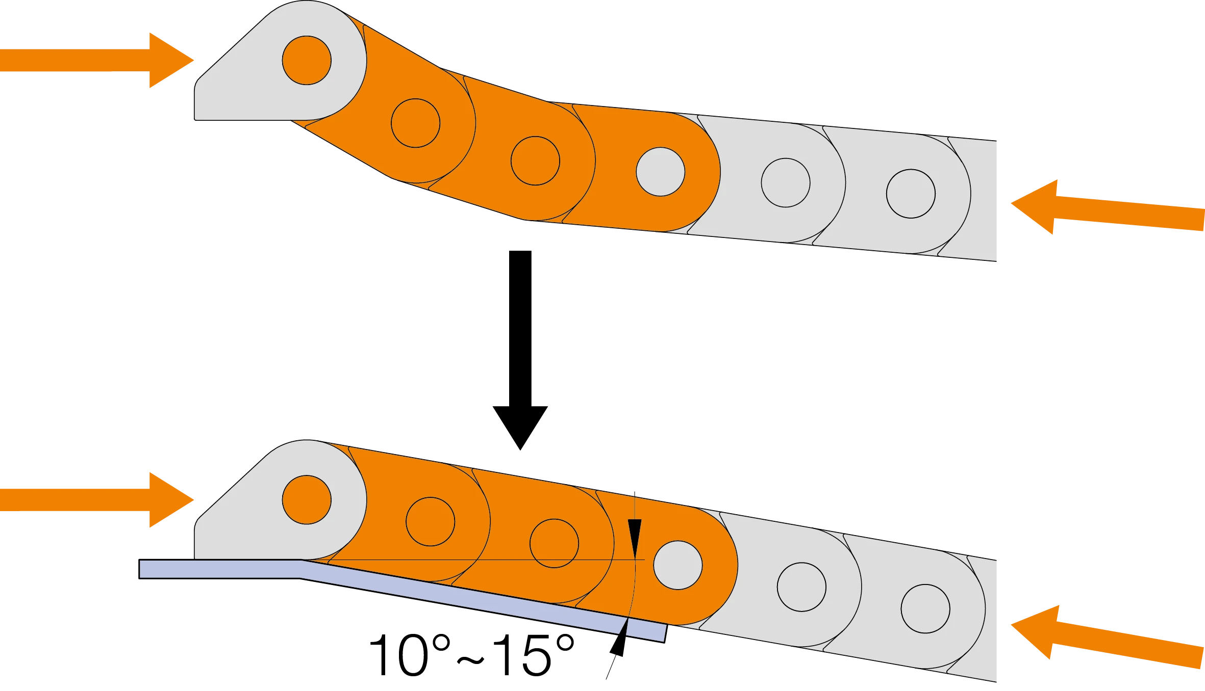
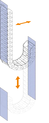
B. With single-sided support

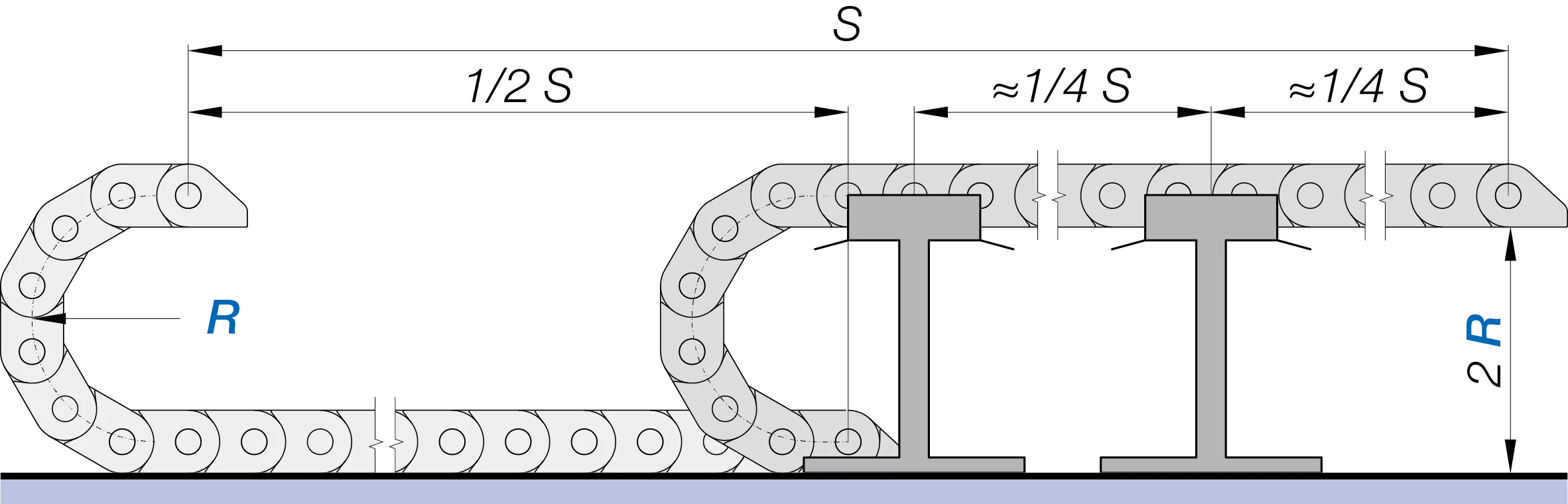
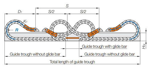
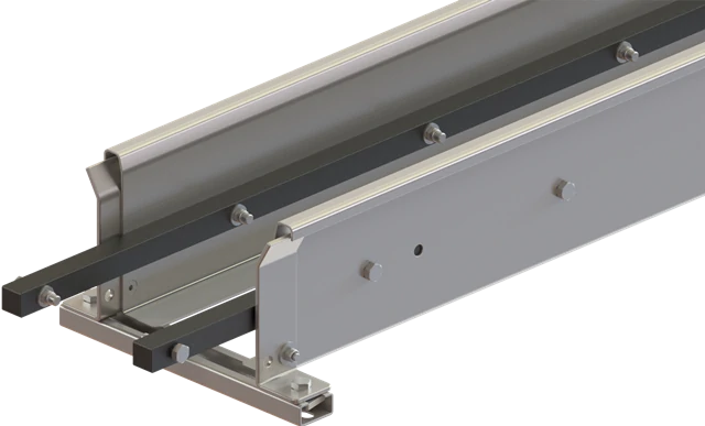
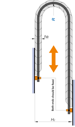
C. With overall support

Distribution rules of cables and hoses for side-mounted applications:

1. The cables and hoses are distributed from top to bottom in ascending order of weight for high stability

2. Different layers should be separated by locking separators. The cables and hoses can not move freely if using movable separators and wear is increased

Definition:The cable chain is placed on their side and has a circular movement in horizontal direction.

RBR(Reverse Bending Radius) chain can rotate up to 540° along the outer rail or the inner rail. Circular movement in vertical direction is also possible. Guide troughs may be necessary, depending on the applications. Please consult us.

The cable chain is fixed on the inner track and rotates along the outer track.
When the angle of the fixed end β = α * Ra / (Ri + Ra), the drag chain is at its shortest length.

LK = π (β / 180°) * Ri + K

The cable chain is fixed on the outer track and rotates along the inner track.
When the angle of the fixed end β = α * Ri / (Ri + Ra), the drag chain is at its shortest length.

LK = π (β / 180°) * Ra+ K

We recommend pivoting mounting brackets as standard for side-mounted rotary applications.

Pivoting mounting brackets fit the circular rails better.

Distribution rules of cables and hoses for side-mounted applications are applied to side-mounted rotary. The cables and hoses bend in two directions in circular movement which should be distributed in the center of the chain, and only one cable or hose is placed in a separate chamber as far as possible.

Benifits of distribution:

1. Make your equipments more orderly

2. Optimise the chain size and reduce costs

3. Reduce wear of cables and hoses

4. Prevent cables from torsion and breakage

5. Maximize the service life of chain systems

General distribution rules for cables and hoses are as follows. For complex applications, we are happy to provide professional distribution solutions for free, please consult us.

Cables and hoses must have additional clearances to move freely in the chain. Different minimum clearances are as follows:

Round electrical cables: 10% of diameter
Flat electrical cables: 10% of width/thickness each
Hydraulic hoses: 20% of diameter
Pneumatics hoses: 5-10% of diameter
Please note: Don't fill chain more than 80%!

General distribution rules for cables and hoses are as follows. For complex applications, we are happy to provide professional distribution solutions for free, please consult us.

For horizontal or vertical applications, the cable/hose weight should be symmetricaly distributed along the width of the chain, with the heaviest cables/hoses laying on the outside. Even loading can help the chain to achieve its maximum service life.

For side-mounted applications, the cables/hoses should be distributed from top to bottom in ascending order of weight for high stability. Different layers should be separated by locking separators.

Distribution rules of different cables and hoses

1.Cables and hoses with different outer jacket materials must be separated to avoid sticking together. Electrical cables and hydraulic/pneumatics hoses should be separated, cables of different voltages should be separated.

2.It is beneficial to place each cable and hose in a separate chamber if the space is allowable.

3.Two flat cables placed side by side should be separated by vertical separators, and when stacked should be separated by horizontal separators. Flat and round cables should be laid separately in the chain.

4.Sufficient room must be left in the chain for hydraulic hoses because of the expansion or contraction during pressure changes. As lateral movements of the hydraulic hoses can lead to increased abrasion, we recommend locking separators for the fixed position.


Distribution rules for multiple cables

1. d1 + d2 > 1.2 hi

A separator is not required

2. d1 + d2 ≤ 1.2 hi

A vertical separator is required or a horizonal separator must be used to reduce the inner height

3. d1 > 0.5 d2

A horizontal separator is not required for two stacked cables

4. d1 ≤ 0.5 d2

A horizontal separator must be required for two stacked cables

Cables and hoses must be able to move freely within the cable carrier without tension at the bending radius. They should be secured with strain relief devices at both ends. As hydraulic hoses expand or contract during pressure changes, only one-sided strain relief is applied at the moving end.

The bending radius R of the cable chain should not be less than the minimum bending radius allowed for the internal pipelines, which usually depends on the thickest or stiffest cable or hose. Selecting a bending radius higher than the minimum value can increase the service life.

Cable: Rmin ≈ 7.5-10 x d
Pneumatics hose: Rmin ≈ 10-12 x d
Hydraulic hose:Rmin ≈ 10-15 x d